|
Retrotec Blower Door and DM-2 Digital Manometer
The Retrotec blower door is designed to be used to pressure test a house. Like other blower door testers, the fan mounts in a door to the outside. The DM-2 manometer is used to control the flow through the fan, ideally depressurizing the house to 50 pascals. At that point the airflow will have overcome any natural pressures or leaks in the house and can be used as a reference. The blower door test can be extremely useful in determining where time should be spent in tightening up the house to save money and energy for the homeowner.
The instructions that come with the door frame are pretty clear in how it should be assembled and mounted. Some auditors keep the frame assembled and reduced to its minimum dimensions so that set up on-site is quick. (This includes the cross bar that supports the fan.) Others keep the frame completely disassembled and in the carrying case. Whichever method works best for you is fine. It is important to be consistent in whatever process you use so that all the pieces will be available at the home. Since the fan will be in an open doorway, keeping the door open for the shortest possible time will be beneficial for the homeowner.
Some auditors lay the frame down on the floor to install the fabric cover. Space is not always available for that. It is common to lean the frame up against the house door and stretch the fabric over it.
NOTE: Make sure to locate the manometer hose to the exterior before the final installation of the door in the frame. Otherwise you may find yourself crawling through the fan hole! Make sure that the hose end is not going to be affected by wind or rain or the flow through the fan. Locate it off to the side and consider laying a wet sponge on top to protect it from the elements. (The sponge is wet to keep it from blowing away.)
I have found that the easiest way to get the fabric stretched around the fan is to kneel in front of the fan and reach down to the bottom on either side and stretch the fabric evenly up each side.
 The DM-2 manometer and control will automatically control the speed of the fan to depressurize the house. The hose connections are color coded with the hose harness that comes with the blower door - the red hose goes to the outside and to the red connection on the manometer, the yellow hose connects to the yellow fitting on the fan and the manometer. There is a DC power connection that charges the batteries in the manometer as long as the fan is plugged into an AC outlet. And there is a computer type connection that regulates the speed of the fan. and provides other information to the manometer.
The pressures displayed on a digital manometer like the DM-2 indicate a pressure difference: the pressure at one point with reference to the pressure at another point. That's why each manometer channel has two possible connections. When making connections to a digital manometer, always go through the exercise of thinking, "I want to measure the pressure here WITH REFERENCE TO the pressure there." The connection to the Reference point attaches to the Reference tap. So if you want to measure the pressure in the house WITH REFERENCE TO (WRT) the outside of the house, the outside hose attaches to a Reference tap on the manometer (the red tap on the DM-2), usually on Channel A.
 In the process of doing the blower door test, Channel A is used to measure the pressure in the house WRT the outside and Channel B is used to measure the airflow through the fan. (The manometer calculates the airflow by knowing the size of the opening and the pressure difference across the fan.)
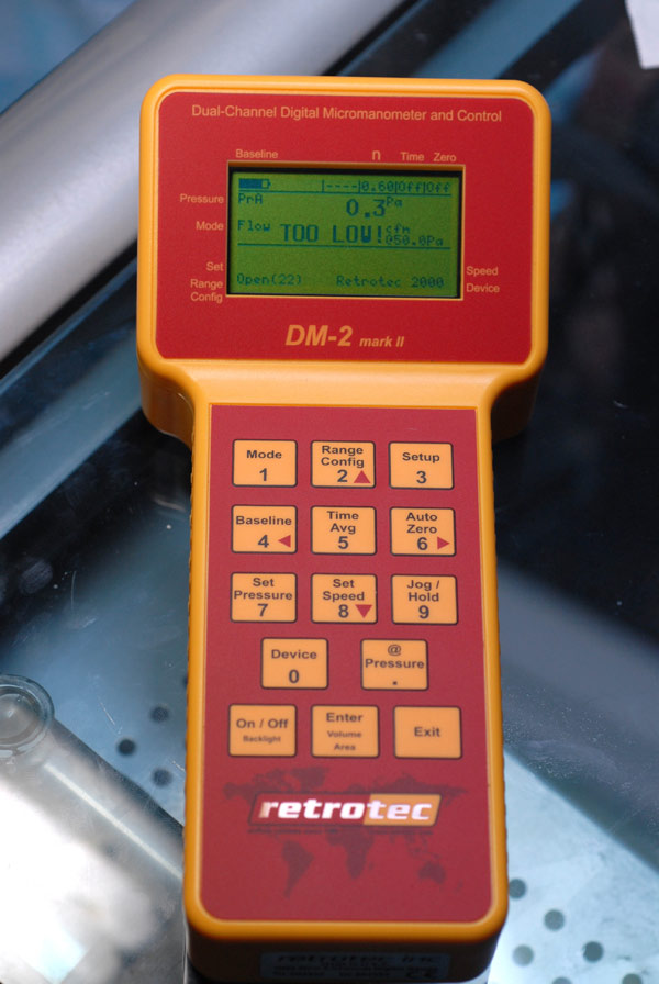
When you first turn on the DM-2, a map of the world overlaid by the Retrotec logo appears. Pushing any button will terminate that screen and display the operating screen. Initially the state of the battery is indicated in the upper left corner. To the right of that will be a small area with "----" in it. This is used to for the "Jog"/"Hold" indicator. To the right of that is an area identified as "n" in the printing on the manometer. This is a "slope" indicator normally about 0.65. When the fan cannot get the house to a CFM50 reading, this is a typical slope that the manometer will use to estimate where the @50 reading should be. Retrotec has software that will allow multiple points to be taken that will provide a more accurate slope number for a specific house. The manometer can be plugged into a computer for an automatic test. The software is known as "Door Fan" and can be downloaded from the Retrotec web site at: http://www.retrotec.com/products/software/door_fan_30/ Their liscensing is a bit sketchy so you may have to call them.
The next slot is indicated as "Time" on the label. When the "Time Avg" button is pressed to space out the readings, the time between readings will be indicated here. Off, 1s, 2s, 4s, 8s, 10s, 20s, 1m, and 2m. The longer readings are particularly useful if it is a windy day outside and the readings are bouncing around a lot.
The next slot is marked as "Zero". This is indicates whether the Auto Zero function is switched on or off. Automatic zeroing takes some power so you may want to switch this off with the "Auto Zero" button (also marked '6') if you are operating the manometer on its internal batteries. When the manometer is attached to the door the batteries are continuously charged through its electrical connection.
Blower Door Test
The Retrotech DM-2 blower door configuration comes with a bundled cable that includes a long red hose, a shorter yellow hose, a yellow computer cable, and an electrical, charging cable. The long end of the red hose should be run through the hole in the door fabric and placed out of the airflow outside the house. The other end of the red hose connects to the "Ref A" connector on the DM-2. The yellow hose should be connected to the pressure terminal on the fan and to the "Ref B" connector on the DM-2. The communication cable connects to the jack on the fan and the jack on the DM-2. The low voltage power cable connects to the connectors on the fan and manometer. Connect the power cable to the fan and a working power source.
|